Difference between revisions of "Asp"
| Line 16: | Line 16: | ||
The Asp system is comprised of 2 PCBs, the main PCB and a daughter board called Juno which contains the sound modules along with the Mako IR battle chip. Juno fits onto the main board using headers and can be secured using 11mm (or 10 mm and a washer) nylon spacers. Nylon spacers are recommended to avoid any possibilities of a short circuit. | The Asp system is comprised of 2 PCBs, the main PCB and a daughter board called Juno which contains the sound modules along with the Mako IR battle chip. Juno fits onto the main board using headers and can be secured using 11mm (or 10 mm and a washer) nylon spacers. Nylon spacers are recommended to avoid any possibilities of a short circuit. | ||
| − | + | ===Mainboard Walkaround===<br> | |
<center> | <center> | ||
[[File:Asp VX labels.jpg]] | [[File:Asp VX labels.jpg]] | ||
| Line 33: | Line 33: | ||
Along the bottom of the main board are the male header connections for the Juno board. The red two pin connectors are 5V or Battery Voltage supply pins. PLEASE take care not to accidentally short these pins if the JUNO board is not present (such as in the testing procedure). The 5 pin header carries the signal information to and from the main board and Juno. To enter testing mode the Juno board is removed and a typical receiver bind plug is placed on the innermost pin and middle pin. For further info refer to the Testing Procedure section. | Along the bottom of the main board are the male header connections for the Juno board. The red two pin connectors are 5V or Battery Voltage supply pins. PLEASE take care not to accidentally short these pins if the JUNO board is not present (such as in the testing procedure). The 5 pin header carries the signal information to and from the main board and Juno. To enter testing mode the Juno board is removed and a typical receiver bind plug is placed on the innermost pin and middle pin. For further info refer to the Testing Procedure section. | ||
| + | The bottom left corner features the receiver input connector. This requires the receiver connection cable as supplied with Asp. The pinouts are as follows from the top. | ||
| + | V0 - Black wire<br> | ||
| + | 5V+ - Red wire<br> | ||
| + | CH1 - White wire<br> | ||
| + | CH2 - Yellow wire<br> | ||
| + | CH3 - Orange wire<br> | ||
| + | CH4 - Green wire<br> | ||
| + | CH5 - Blue wire<br> | ||
| + | CH6 - Purple wire<br> | ||
| + | CH7 - Grey wire<br> | ||
| + | |||
| + | Operational modes for the channels are as follows: | ||
===Receiver Connections 4 Channel Operation=== | ===Receiver Connections 4 Channel Operation=== | ||
Revision as of 07:00, 5 September 2015
NOTE: The ASP Wiki is currently UNDER CONTRUCTION
Welcome to the Asp Wiki Page. This site serves as the online manual for the Asp control board. For various reasons there is no printed manual as such for Asp. This page along with the Asp Forum Topic and the Asp Youtube Playlist serve as the online reference source for Asp.
What is Asp?
Asp is essentially a radio controlled quad motor controller designed for use in 1/16th scale tanks. HOWEVER, in reality Asp is flexible enough for use in halftrack vehicles, fully wheeled vehicles and even boats/watercraft. Use of Asp in non tracked vehicles is covered in an upcoming section. For now let's just concentrate on tanks.
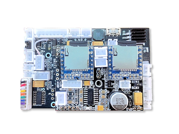
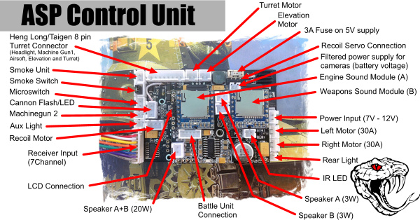
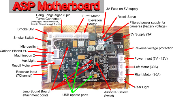
From inception, Asp has been designed as a simple plug and play replacement unit for existing Heng Long and Taigen Tank control units. As the picture below shows Asp shares many of the same style connectors as found on Heng Long and Taigen tanks including the somewhat standard 8-pin turret connector.
Asp is controlled by hobby standard R/C signals and thus will require the use of a true R/C radio and receiver. To make use of all of the available features on Asp an 8 channel programmable radio is suggested. However as of September 15 Asp can now be controlled with both 4 channel and 6 channel radio setups. Asp is supplied with a special cable for connecting the receiver to the mainboard.
Asp Main MFU
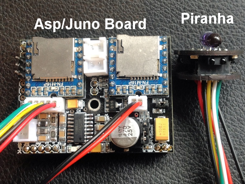
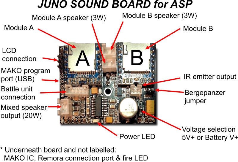
The Asp system is comprised of 2 PCBs, the main PCB and a daughter board called Juno which contains the sound modules along with the Mako IR battle chip. Juno fits onto the main board using headers and can be secured using 11mm (or 10 mm and a washer) nylon spacers. Nylon spacers are recommended to avoid any possibilities of a short circuit.
===Mainboard Walkaround===
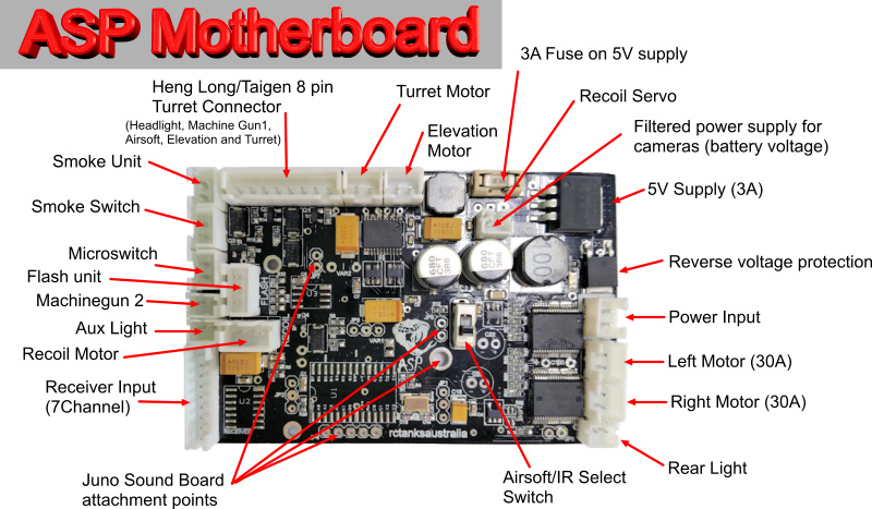
Ok starting in the top right corner is the 5 volt Low Drop Out voltage regulator that powers Asp's micro controllers, LEDs, the receiver unit and servos like the recoil servo. The output capacity is 3 Amps which is enough to drive additional servos connected to the receiver. This regulator WILL run hot and when mounting Asp please make sure that there is some space around this corner for cooling.
Moving clockwise we have the blue power LED and reverse polarity protection FET. When powered up the blue LED will turn on. PLEASE NOTE this LED indicates power at the input and does NOT indicate power supply after the 5V regulator. Hence this LED will still light up if the 5V fuse has blown or if there is any other issue on the 5V supply circuit. To monitor the 5V supply line there is a blue LED indicator on the JUNO board. The reverse polarity FET provides some protection for Asp if the power supply is accidentally connected in reverse.
The Power Input consists of a JST-XH style connector which unlike the picture above should be coloured red. This connection is compatible with the power input for Heng Long and Taigen tanks. If in doubt about the polarity look on the underside of the Asp board. In general V+ pads are square or rectagonal, whereas V0 pads are round or oval.
Below the input are the JST-XH style connectors for the main drive motors and immediately behind these are the STI 30 Amp motor controller ICs. For easy of setup when placed behind a typical tank motor setup the left connector connects to the left motor and the right to the right motor.
The bottom left corner contains the connection for a reverse light. This is a smaller JST-PH style connector as found on the Taigen MFU. Heng Long tanks if they do feature a reverse light have a larger JST-XH connector. One can use a supplied JST-PH lead to make a connection the Heng Long reverse light.
Along the bottom of the main board are the male header connections for the Juno board. The red two pin connectors are 5V or Battery Voltage supply pins. PLEASE take care not to accidentally short these pins if the JUNO board is not present (such as in the testing procedure). The 5 pin header carries the signal information to and from the main board and Juno. To enter testing mode the Juno board is removed and a typical receiver bind plug is placed on the innermost pin and middle pin. For further info refer to the Testing Procedure section.
The bottom left corner features the receiver input connector. This requires the receiver connection cable as supplied with Asp. The pinouts are as follows from the top.
V0 - Black wire
5V+ - Red wire
CH1 - White wire
CH2 - Yellow wire
CH3 - Orange wire
CH4 - Green wire
CH5 - Blue wire
CH6 - Purple wire
CH7 - Grey wire
Operational modes for the channels are as follows:
Receiver Connections 4 Channel Operation
Channel 1 Steering White
Channel 2 Throttle Yellow
Channel 3 Gun elevation & Weapons control Orange
Channel 4 Turret Green
Receiver Connections 6 Channel Operation
Channel 1 Steering White
Channel 2 Throttle Yellow
Channel 3 Gun elevation & Weapons control Orange
Channel 4 Turret Green
Channel 5 Switching Blue
Channel 6 Sound control Purple
Receiver Connections 7 Channel Operation
Channel 1 Steering White
Channel 2 Throttle Yellow
Channel 3 Gun elevation Orange
Channel 4 Turret Green
Channel 5 Switching Blue
Channel 6 Sound control Purple
Channel 7 Weapons Grey
ASP Terminology & General Radio Programming Basics
Since most users will be upgrading to a true hobby grade R/C system to use ASP a basic understanding of how this system work will be of great advantage. In particular knowing what is sent from the outputs of your receiver and how servos or control boards like ASP respond will help immensely. This is what will be concentrated on here.
When your receiver gets information from your radio it splits this information up into the individual channels and sends it onto your control board, ESC or servos. All this information consists of is a single 'on' pulse of between 1 and 2 milliseconds repeated every 20 milliseconds. It is simply the amount of time that the pulse is on that tells the servo or control board what to do. In the case of servos a pulse of 1 millisecond will send the servo fully left and a pulse of 2 milliseconds sends the servo fully right. A pulse of 1.5 milliseconds is exactly in the middle and hence the servo will move to the mid point or NEUTRAL position. Since 1.5 is a rather odd number to work with it is easier to refer to the neutral position as 0 even though it represents a pulse of 1.5 ms. Calling the neutral position 0% is somewhat better as it represents a zero amount of displacement left or right. The full extent of travel left may then be termed -100% and the full extent of right travel +100% . Thus a pulse of 1 ms becomes -100% and 2 ms becomes +100%. The instructions for ASP use this convention. The table below demonstrates how the various pulse width signal on CH5 control the functions of ASP.
|
Pulse Width (ms) |
% |
Start Function |
Operational Function |
|
1.00 - 1.20 |
-100 |
Engine Start 4 |
Headlight on/off |
|
1.21 - 1.25 - 1.30 |
-50 |
Engine Start 3 |
Aux light on/off |
|
1.31 - 1.50 - 1.70 |
0 |
||
|
1.71 - 1.75 – 1.80 |
+50 |
Engine Start 2 |
Smoke unit on/off |
|
1.81 - 2.00 |
+100 |
Engine Start 1 |
Engine off/Tank shutdown |
Consequently, the “ON” signal for Asp is referred to as CH5 +100%. This means that to turn Asp “ON” Asp is looking for a pulse of between 1.8 and 2 milliseconds on Channel 5. When such a pulse is received Asp will “turn on” . If CH 5 is then returned to the neutral position we can continue to use the channel to receive more commands. Likewise if CH5 is in neutral when the tank is powered up we can use the 100% signal as a switch to turn the tank on when it is desired to do so.
If you wish to use a radio other than a 9X or Taranis series radio you will need to refer to your own radio manual as to how to assign switches to channels and what values to output for a particular switch position.
In summary, to set up a switch on your radio to control a function on Asp you must: 1. Set one position of the switch to output a neutral signal (0% ie: around 1.5 ms) 2. Set the second position of the switch to output the desired activation signal To operate start with switch in position 1. Activate the desired function by moving switch to position 2 and then return the switch to position 1 (toggle).
This information is important if you are programming your own radio switches to control Asp. Remember, if you are using a 9XR series or Taranis radio all of the settings for Asp can be downloaded and transferred to you computer via (USB). It is al done for you :). Knowing the above will help you if you wish to change from the default ASP radio settings.
JUNO sound board for Asp
Details of the Juno sound board
Sound Lists
Below are lists of sounds for both Module A and B
Module A
| FILE # | Module | Model | Name | Description |
| 1 | A | Model | EngStart-1 | Engine Start Variant 1 |
| 2 | A | Model | EngStart-2 | Engine Start Variant 2 |
| 3 | A | Model | EngStart-3 | Engine Start Variant 3 |
| 4 | A | Model | EngStart-4 | Engine Start Variant 4 |
| 5 | A | Model | Shutdwn-1 | |
| 6 | A | Model | Shutdwn-2 | |
| 7 | A | Model | Shutdwn-3 | |
| 8 | A | Model | Shutdwn-4 | |
| 9 | A | Model | ShutdwnB | |
| 10 | A | Model | EngIdle-A | |
| 11 | A | Model | MotionStrt | |
| 12 | A | Model | Speed-a140 | |
| 13 | A | Model | Speed-b135 | |
| 14 | A | Model | Speed-c130 | |
| 15 | A | Model | Speed-d125 | |
| 16 | A | Model | Speed-e120 | |
| 17 | A | Model | Speed-f115 | |
| 18 | A | Model | Speed-g110 | |
| 19 | A | Model | Speed-h105 | |
| 20 | A | Model | Speed-i100 | |
| 21 | A | Model | Speed-j095 | |
| 22 | A | Model | Speed-k090 | |
| 23 | A | Model | Speed-l085 | |
| 24 | A | Model | Speed-m080 | |
| 25 | A | Model | Speed-n075 | |
| 26 | A | Model | Speed-o070 | |
| 27 | A | Model | Speed-p065 | |
| 28 | A | Model | Speed-q060 | |
| 29 | A | Model | MotionStop | |
| 30 | A | Model | EngIdleB | |
| 31 | A | Model | MtnStrtB | |
| 32 | A | Model | DSpeed-1 | |
| 33 | A | Model | DSpeed-2 | |
| 34 | A | Model | DSpeed-3 | |
| 35 | A | Model | MotionStopB | |
| 36 | A | Model | TankFire | |
| 37 | A | Model | Welcome |
Module B
File No. Description
001 gun elevation
Sound Sets
Latest sound sets for Asp can be downloaded here. Note: These files below are disk image files and require writing to 2GB micro SD Cards using appropriate Disk Imaging software (Active @ Disk Image Freeware is what these files were created with)
Tiger 1
Module A [1]
Module B [2]
T-34
Module A
Module B
IR Battle Capability
Details of the IR functions of the MAKO chip
